
Page 74 - DryLite® Dryers
P. 74
®
DRYLITE DRYER
Chapter 6: Installation of DryLite® - Side Flip Air Cannons™
Frame Assembly
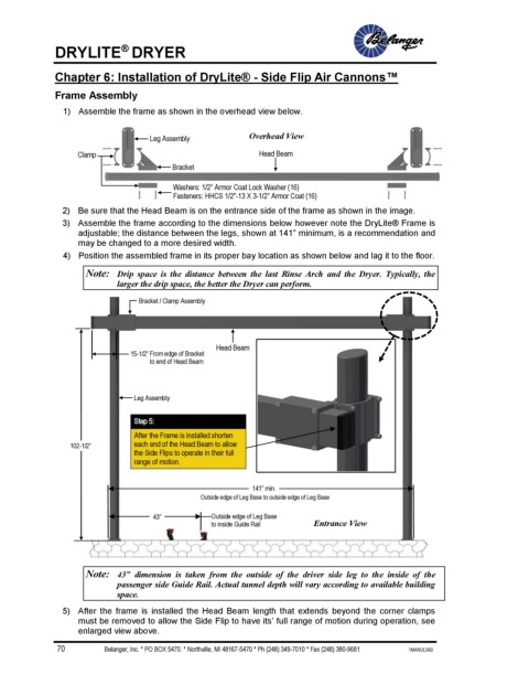
1) Assemble the frame as shown in the overhead view below.
Leg Assembly Overhead View
Clamp Head Beam
Bracket
Washers: 1/2” Armor Coat Lock Washer (16)
Fasteners: HHCS 1/2"-13 X 3-1/2” Armor Coat (16)
2) Be sure that the Head Beam is on the entrance side of the frame as shown in the image.
3) Assemble the frame according to the dimensions below however note the DryLite® Frame is
adjustable; the distance between the legs, shown at 141” minimum, is a recommendation and
may be changed to a more desired width.
4) Position the assembled frame in its proper bay location as shown below and lag it to the floor.
Note: Drip space is the distance between the last Rinse Arch and the Dryer. Typically, the
larger the drip space, the better the Dryer can perform.
Bracket / Clamp Assembly
Head Beam
15-1/2” From edge of Bracket
to end of Head Beam
Leg Assembly
Step 5:
After the Frame is installed shorten
102-1/2” each end of the Head Beam to allow
the Side Flips to operate in their full
range of motion.
141” min.
Outside edge of Leg Base to outside edge of Leg Base
43” Outside edge of Leg Base
to inside Guide Rail Entrance View
Note: 43” dimension is taken from the outside of the driver side leg to the inside of the
passenger side Guide Rail. Actual tunnel depth will vary according to available building
space.
5) After the frame is installed the Head Beam length that extends beyond the corner clamps
must be removed to allow the Side Flip to have its’ full range of motion during operation, see
enlarged view above.
70 Belanger, Inc. * PO BOX 5470. * Northville, MI 48167-5470 * Ph (248) 349-7010 * Fax (248) 380-9681 1MANUL960