Page 72 - DryLite® Dryers
P. 72

®
              DRYLITE DRYER

              Chapter 5: Installation of DryLite® - Top Flip Air Cannons™

              20HP Top Flip Nozzle Frame Housings
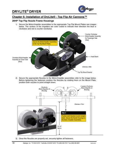
                 1)  Secure the Motor/Impeller assemblies to the appropriate Top Flip Mount Plates see images
                     below. The centers of the Impellers are color coded to indicate their direction the blue is
                     clockwise and red is counter-clockwise.


                                                                                          Counter-Clockwise
                                                                                          Motor/Impeller Assembly
                                                                                          for Passenger Side
                                   Step 1:
                                                                                          (Red)
                                   Secure the Motor/Impeller Assemblies
                                   to the Top Flip Mount Plates.


                                                                                                 Head Beam
              Clockwise Motor/Impeller
              Assembly for Driver Side
                    (Blue)

                                                                                       Entrance Side


                                                                                   Top Flip Mount Bracket

                 2)  Secure the appropriate Nozzles to the Motor/Impeller assemblies refer to the image below.
                     Before tightening the fasteners position the Nozzles by rotating them on the Mount Plate;
                     position both nozzles to point straight down.

                                                                                     Counter-Clockwise
                                            Clockwise                                 Motor/Impeller &
                                         Motor/Impeller &                                Housing
                                            Housing


                                                                               Entrance View
                                                                     0


                                                                  Step 2:
                                                                  Position both Nozzles to point straight
                                                                  down. Secure the Nozzle Housings to
                                                                  the Motor /Impeller Assemblies.


                                                             93-1/4”
                                                             Approx.


                 3)  Once the Nozzles are properly set, securely tighten all fasteners.

              68                         Belanger, Inc. * PO BOX 5470. * Northville, MI 48167-5470 * Ph (248) 349-7010 * Fax (248) 380-9681                                        1MANUL960
   67   68   69   70   71   72   73   74   75   76   77