
Page 18 - TopWinder®
P. 18
®
®
TopWinder
Installation
Frame Assembly
Attaching the Legs
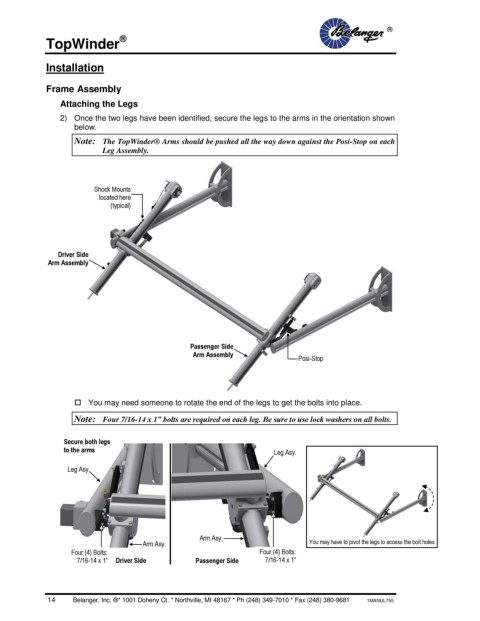
2) Once the two legs have been identified, secure the legs to the arms in the orientation shown
below.
Note: The TopWinder® Arms should be pushed all the way down against the Posi-Stop on each
Leg Assembly.
Shock Mounts
located here
(typical)
Driver Side
Arm Assembly
Passenger Side
Arm Assembly Posi-Stop
You may need someone to rotate the end of the legs to get the bolts into place.
Note: Four 7/16-14 x 1” bolts are required on each leg. Be sure to use lock washers on all bolts.
Secure both legs
to the arms Leg Asy.
Leg Asy.
Arm Asy.
Arm Asy. You may have to pivot the legs to access the bolt holes
Four (4) Bolts: Four (4) Bolts:
7/16-14 x 1” Driver Side Passenger Side 7/16-14 x 1”
14 Belanger, Inc. ®* 1001 Doheny Ct. * Northville, MI 48167 * Ph (248) 349-7010 * Fax (248) 380-9681 1MANUL755