
Page 37 - Top Wheel Mix & Match
P. 37
TOP WHEEL Mix and Match
Installation
Auto Retract Option Installation (if applicable)
Wiring for Optional Auto Retract
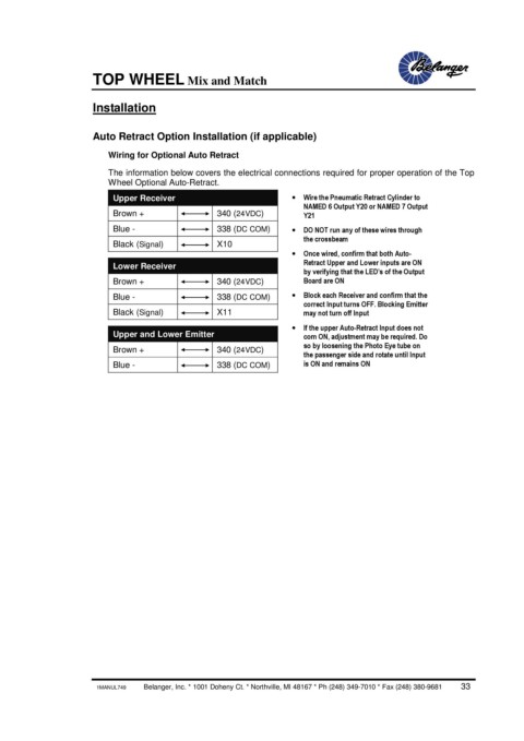
The information below covers the electrical connections required for proper operation of the Top
Wheel Optional Auto-Retract.
Upper Receiver · Wire the Pneumatic Retract Cylinder to
NAMED 6 Output Y20 or NAMED 7 Output
Brown + 340 (24VDC) Y21
Blue - 338 (DC COM) · DO NOT run any of these wires through
the crossbeam
Black (Signal) X10
· Once wired, confirm that both Auto-
Lower Receiver Retract Upper and Lower inputs are ON
by verifying that the LED’s of the Output
Brown + 340 (24VDC) Board are ON
Blue - 338 (DC COM) · Block each Receiver and confirm that the
correct Input turns OFF. Blocking Emitter
Black (Signal) X11 may not turn off Input
· If the upper Auto-Retract Input does not
Upper and Lower Emitter com ON, adjustment may be required. Do
so by loosening the Photo Eye tube on
Brown + 340 (24VDC)
the passenger side and rotate until Input
Blue - 338 (DC COM) is ON and remains ON
1MANUL749 Belanger, Inc. * 1001 Doheny Ct. * Northville, MI 48167 * Ph (248) 349-7010 * Fax (248) 380-9681 33