
Page 48 - AirBlade® Dryer Signature® Series
P. 48
AIRBLADE® DRYER Signature ® Series
Installation
AirBlade® Express, Frame Assembly
20) Repeat steps 16, 17 and 18 for the driver side, but using the clockwise motor and housing.
21) Locate the AirBlade® Express accessory box and remove the following parts:
Item Qty Item Qty
White Cover for Oval Extrusion 4 1/4-20 x 1” HHCS 8
3/4” Round Velcro Hook 8 1/4” Lock Washer 8
3/4” Round Velcro Loop 8 3/4” Rod for Corner Cover 8
Cover for Oval Extrusion Velcro Pieces and Cover for Oval Extrusion
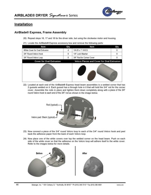
22) Located at each end of the AirBlade® Express head beam assemblies is a welded corner that has
2 gussets welded on it. Each gusset has a through hole in it that will hold the 3/4” rod for the corner
cover. Assemble the rods in place and tighten them down completely along with a piece of the 3/4”
round Velcro hook to each end of the 3/4” rod as shown in the image below.
Rod (typical)
Velcro pad: Black (typical)
23) Now connect a piece of the 3/4” round Velcro loop to each of the 3/4” round Velcro hook and peel
back the adhesive paper from the back of each Velcro loop.
24) Now place one of the white covers over top the welded corner on the head beam. Push on each
side of the white cover so that the adhesive on the Velcro loop will adhere itself to the white cover.
Refer to the images below for more details.
Before After
44 Belanger, Inc. * 1001 Doheny Ct. * Northville, MI 48167 * Ph (810) 349-7010 * Fax (810) 380-9681 1MANUL009