
Page 43 - AirBlade® Dryer Signature® Series
P. 43
AIRBLADE® DRYER Signature ® Series
Installation
AirBlade® Express, Frame Assembly
2) Determine which side of the bay has more room for you to drive your forklift. If you will be coming in
from the exit side of the bay, you will need to place the entrance head beam assembly (angled
housings) on first. If coming from the entrance side of the bay, you will need to place the exit head
beam on first.
3) Once you have determined which side of the bay you will be working from, locate the skid that has
the AirBlade® Express head beams shipped on. Remove all hardware from the skid except for the
head beam assembly that you will be mounting first. Determine which side of the head beam you
need to pick up from and place the forks of the forklifts through the supplied forklift clamps and lift
up just enough so that the forks are tight in the clamps. Remove the 8 shipping lags that are
holding the head beam to the skid.
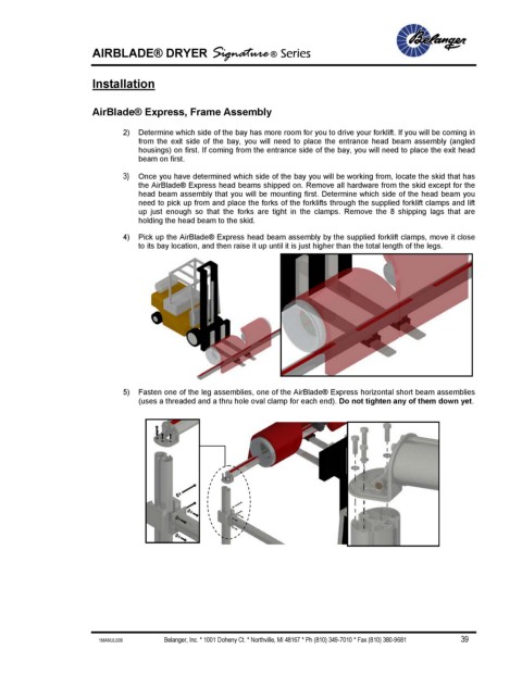
4) Pick up the AirBlade® Express head beam assembly by the supplied forklift clamps, move it close
to its bay location, and then raise it up until it is just higher than the total length of the legs.
5) Fasten one of the leg assemblies, one of the AirBlade® Express horizontal short beam assemblies
(uses a threaded and a thru hole oval clamp for each end). Do not tighten any of them down yet.
1MANUL009 Belanger, Inc. * 1001 Doheny Ct. * Northville, MI 48167 * Ph (810) 349-7010 * Fax (810) 380-9681 39