
Page 42 - AirBlade® Dryer Signature® Series
P. 42
AIRBLADE® DRYER Signature ® Series
Installation
AirBlade® Express, Pre-Installation Notes
• Before you begin the assembly of the AirBlade® Express frame, notice how one of the 2 head beams that shipped
has the plastic housings on a 10° angle. This head beam must be on the entrance side of the bay with the flat
portions of the housings facing the entrance. The other head beam will have the flat portions of the housings facing
the exit of the bay.
• Assemble the frame as shown in the steps & views below.
AirBlade® Express, Frame Assembly
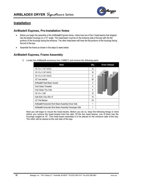
1) Locate the AirBlade® accessory box (108627) and remove the following parts:
Item Qty Oval Clamps
1/2-13 x 1-1/2” HHCS 16
1/2-13 x 3 1/4” HHCS 16
1/2-13 x 5-1/2” HHCS 8
1/2” lock washer 56
AirBlade® Head Beam Gusset 4
Oval Clamp Threaded 4
Oval Clamp Thru Hole 4
1/2-13 x 1-3/4” 16
Kwik-Bolt 3 Zinc 5/8 x 6” 16
1/2” Flat Washer 24
AirBlade® Horizontal Short Beam Assembly Driver Side 1
AirBlade® Horizontal Short Beam Assembly Passenger Side 1
Next you will begin to mount the head beams. Before you do so, keep the following things in mind
before you remove the head beams from the skid. Of the two head beams, one of them has the
housings angled at 10°. This head beam assembly is to be placed on the entrance side of the bay.
The other will be placed at the exit side of the bay.
38 Belanger, Inc. * 1001 Doheny Ct. * Northville, MI 48167 * Ph (810) 349-7010 * Fax (810) 380-9681 1MANUL009