
Page 1569 - Foton Workshop Manual - Auman EST-M
P. 1569
Electrical system –circuit EL - 145
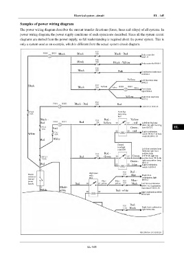
Samples of power wiring diagram IN
The power wiring diagram describes the current transfer directions (fuses, fuses and relays) of all systems. In
power wiring diagram, the power supply conditions of each system are described. Since all the system circuit DI
diagrams are started from the power supply, so full understanding is required about the power system. This is
only a system used as an example, which is different from the actual system circuit diagram.
EG
Black Black Black - Red Body controller
B061-11
TR
Black Black - Yellow Body controller B060-1
Black Pink Combination instrument AX
A B014-2
Yellow Left front step lamp
B002-2 FR
Black Black Yellow
Yellow
Yellow
Front dome
light D004-2
ST
Yellow Right front step lamp
B017-2
Black - Red Red BR
Front fog
lamp relay
R09 BW
Black - Red - Yellow
Red Red Yellow - red Left front fog lamp
B001-2& right front fog
Red Green - lamp B072-2 EL
red Light combination
White switch B034-17 & body
controller B061-18
Red White
Dipped
headlight
relay R08 Left front position lamp
B004-8& right front
Red - position lamp
Red Green Green B-070-8& right rear
position lamp H012-4&
Green - right rear position lamp
Red blue H011-4
Light combination
switch A B034-5
Red -
High beam
Master relay blue Right front
switch of R14 combination light
manual Blue - B070-3
power Blue - Blue -
supply Red yellow yellow black Left front combination
B004-3 & Combination
Black- instrument B B015-18
White white Red- white
Light combination switch
B034-3&6
Red-
black Right front combination
light B070-2&6
EL-145