
Page 1631 - Foton Workshop Manual - Auman EST-M
P. 1631
Electrical system –circuit EL - 207
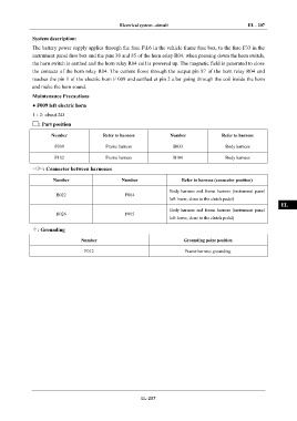
System description: IN
The battery power supply applies through the fuse F\L6 in the vehicle frame fuse box, to the fuse F33 in the
instrument panel fuse box and the pins 30 and 85 of the horn relay R04. when pressing down the horn switch, DI
the horn switch is earthed and the horn relay R04 coil is powered up. The magnetic field is generated to close
the contacts of the horn relay R04. The current flows through the output pin 87 of the horn relay R04 and
EG
reaches the pin 1 of the electric horn F 009 and earthed at pin 2 after going through the coil inside the horn
and make the horn sound.
TR
Maintenance Precautions
● F009 left electric horn
AX
1 - 2: about 2Ω
: Part position
FR
Number Refer to harness Number Refer to harness
F009 Frame harness B033 Body harness
ST
F102 Frame harness B100 Body harness
: Connector between harnesses BR
Number Number Refer to harness (connector position)
BW
Body harness and frame harness (instrument panel
B022 F004
left lower, close to the clutch pedal)
EL
Body harness and frame harness (instrument panel
B026 F005
left lower, close to the clutch pedal)
: Grounding
Number Grounding point position
F012 Frame harness grounding
EL-207