
Page 1653 - Foton Workshop Manual - Auman EST-M
P. 1653
Electrical system –circuit EL - 229
System description: IN
Battery power supply
The power supply is applied through the fuse F\L5 in the vehicle frame fuse box and the fuse F29 in the DI
instrument panel fuse box, to the pin A7 of the plug & socket connector B043 of the radio player to power the
main part of the radio player to function properly.
EG
Ignition switch power supply
Put the ignition switch into ACC or ON position. The current flows through the fuse F35 in the instrument
TR
panel fuse box, to the pin A4 of the plug & socket connector B043 of the radio player to power the main part
of the radio player to function properly.
AX
Maintenance Precautions
● B043, B044 radio player
FR
B043(A7)- earth: when the ignition switch is at ACC/ON position, the voltage is about 24V.
B043(A4)- earth: the voltage is about 24V.
ST
B043(A8)- grounding: always breakover
● C003 right front door speaker
BR
1-2: resistance is about 4Ω
● D003 right front door speaker
BW
1-2: resistance is about 4Ω
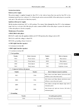
: Part position
EL
Number Refer to harness Number Refer to harness
F015 Frame harness B044 Body harness
F102 Frame harness B100 Body harness
B029 Body harness C003 Left door harness
B043 Body harness D003 Right door harness
: Connector between harnesses
Number Number Refer to harness (connector position)
Body harness and frame harness (instrument panel
B021 F008
left lower, close to the clutch pedal)
Body harness and frame harness (instrument panel
B022 F004
left lower, close to the clutch pedal)
Body harness and right door harness (right side of
B009 C001
instrument panel)
Body harness and right door harness (left side of
B065 D001
instrument panel)
: Grounding
Number Grounding point position
B006 Body left side ground point 2
EL-229