
Page 1658 - Foton Workshop Manual - Auman EST-M
P. 1658
EL - 234 Electrical system –circuit
IN System description:
When the ignition switch is put into the ON/ST position, the current flows to the pin 85 of the IG1 relay R10
DI in the instrument panel fuse box, then goes through coil and is earthed at the pin 86 of the R10. The coil is
powered up to generate magnetic field. The contacts are closed so that the battery current flows through the
fuse F\L3 in the vehicle frame fuse box, to the fuse F05 in the instrument panel fuse box, then to the pin 30 of
EG
the IG1 relay R10. After passing through the contacts, the current is output from the pin 87, flows through the
fuse F05 in the vehicle frame fuse box to the pin 85 of the nitrogen oxides relay R03. Then it passes the coil
TR and is earthed at pin 86 of the R03. The coil is powered up to generate magnetic field, and the contacts are
closed. The output from pin 87 then reaches the pin 1 of the nitrogen oxides sensor and is earthed at the pin 4
of the sensor. The measured amount of nitrogen oxides in exhaust piping is transferred to the engine ECU
AX
module via CAN communication wires. The exhaust related data is measured by the intake air temperature
sensor and the SCR intake air temperature sensor. The engine ECU module controls the adblue pump and the
FR
air solenoid valve is turned on to start injection of the urea solution:
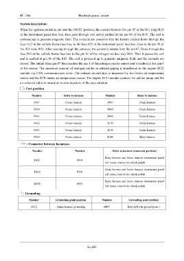
: Part position
ST
Number Refer to harness Number Refer to harness
F057 Frame harness F067 Frame harness
BR
F058 Frame harness F088 Frame harness
BW F061 Frame harness F099 Frame harness
F062 Frame harness F101 Frame harness
EL
F063 Frame harness F105 Frame harness
F065 Frame harness B100 Body harness
: Connector between harnesses
Number Number Refer to harness (connector position)
Body harness and frame harness (instrument panel
B021 F008
left lower, close to the clutch pedal)
Body harness and frame harness (instrument panel
B022 F004
left lower, close to the clutch pedal)
Body harness and frame harness (instrument panel
B026 F005
left lower, close to the clutch pedal)
: Grounding
Number Grounding point position Number Grounding point position
F012 Frame harness grounding B007 Body left side ground point 1
EL-234