
Page 187 - Foton Workshop Manual - Tunland (AT)
P. 187
DIAGNOSTICS - ANTI-LOCK BRAKING SYSTEM (ABS) 04-41
C004008,U160108 BRAKE LAMP SWITCH FAULT
C004008-RELIABILITY FAILURE OF BRAKE LIGHT SWITCH
U160108-BRAKE LIGHT SWITCH NETWORK SIGNAL INVALID
VALUE (CAN SIGNAL)
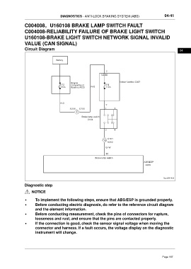
Circuit Diagram 04
Battery
2
C65
Engine Indoor fusebox C037
F2 compartment F4
60 A fusebox A020 R-G 7.5 A
R-G
Y
A306 C105 1 3
4
Brake lamp switch
C004
2 4
C101
18
A302
Gr-W
30
Brake lamp switch
ABS/ESP
A006
ftwxd041439
Diagnostic step
NOTICE
• To implement the following steps, ensure that ABS/ESP is grounded properly.
• Before conducting electric diagnosis, do refer to the reference circuit diagram
and the element information.
• Before conducting measurement, check the pins of connectors for rupture,
looseness and rust, and ensure that the pins are contacted properly.
• If the connection is good, check the sensor signal voltage when moving the
connector and harness. If a fault occurs, the voltage display on the diagnostic
instrument will change.
Page 187