
Page 191 - Foton Workshop Manual - Tunland (AT)
P. 191
DIAGNOSTICS - ANTI-LOCK BRAKING SYSTEM (ABS) 04-45
C006108,C006208-ACCELERATION SENSOR FAULT
C006108-LATERAL ACCELERATION SENSOR SIGNAL FAULT
C006208-LONGITUDINAL ACCELERATION SENSOR SIGNAL
FAULT
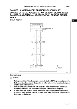
Circuit Diagram 04
Acceleration sensor
Acceleration sensor
1 2 3 D008
Br- Y G-Y V-Y
D301
21 22 23 C401
Br- Y G-Y V-Y
26 27 28 C101
A302
Br- Y G-Y V-Y
32 24 5
Sensor Sensor Sensor
ground Signal power
supply ABS/ESP
A006
ftwxd041443
Diagnostic step
NOTICE
• To implement the following steps, ensure that ABS/ESP is grounded properly.
• Before conducting electric diagnosis, do refer to the reference circuit diagram
and the element information.
• Before conducting measurement, check the pins of connectors for rupture,
looseness and rust, and ensure that the pins are contacted properly.
• If the connection is good, check the sensor signal voltage when moving the
connector and harness. If a fault occurs, the voltage display on the diagnostic
instrument will change.
Page 191