Page 1947 - Foton Workshop Manual - Tunland (AT)
P. 1947

STEERING COLUMN - COMBINATION SWITCH                            51-17

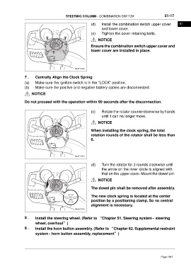
                                                           (d)    Install the combination switch upper cover         51
                                                                  and lower cover.
                                                           (e)    Tighten the cover retaining bolts.
                                                                NOTICE

                                                           Ensure the combination switch upper cover and
                                                           lower cover are installed in place.


                                                 ftwx511049

                 7 .    Centrally Align the Clock Spring
                 (a)    Make sure the ignition switch is in the "LOCK" position.
                 (b)    Make sure the positive and negative battery cables are disconnected.

                      NOTICE

                 Do not proceed with the operation within 90 seconds after the disconnection.


                                                           (c)    Rotate the rotator counterclockwise by hands
                                                                  until it can no longer move.
                                                                NOTICE


                                                           When installing the clock spring, the total
                                                           rotation rounds of the rotator shall be less than
                                                           6.


                                                 ftwx511053

                                                           (d)    Turn the rotator for 3 rounds clockwise until
                                                                  the arrow on the inner circle is aligned with
                                                                  that on the upper cover. Mount the dowel pin.
                                                                NOTICE

                                                           The dowel pin shall be removed after assembly.


                                                           The new clock spring is located at the center
                                                           position by a positioning clamp. So no central
                                                           alignment is necessary.
                                                 ftwx621036

                 8 .    Install the steering wheel. (Refer to “Chapter 51. Steering system - steering
                        wheel, overhaul”)
                 9 .    Install the horn button assembly. (Refer to “Chapter 62. Supplemental restraint

                        system - horn button assembly, replacement”)


                                                                                                        Page 1947
   1942   1943   1944   1945   1946   1947   1948   1949   1950   1951   1952