
Page 2344 - Foton Workshop Manual - Tunland (AT)
P. 2344
71-142 WIRING - SYSTEM CIRCUIT DIAGRAM
Description:
• ESP vehicle stability system uses the wheel speed sensors to detect the
wheel speed and sends the signal to the control module.The control module
adjusts the slip rate of the wheel and keep the wheel running through
increasing or reducing the braking force on the wheel based on the input
wheel speed, which not only prevents the wheels from being locked but also
ensures their steering when the vehicle is under braking conditions. It can
ensure the stability of vehicle's braking and steering and avoid sideslipping
and deviation.
• Signal Input
The ignition switch is in the ON/ST position, the current passes through the fuse
F26 in the indoor fuse box, and the ESP controller pin 28, provides the IG power
supply for the ESP controller.
The battery current is supplied to the ESP pump motor through the engine
71
compartment fuse box F28, F15 to ESP controller.
• Wheel speed signal
The wheel speed signals are alternating signals, which are respectively provided
by four wheel speed sensors: the left front wheel speed sensor, the right front wheel
speed sensor, the left rear wheel speed sensor and the right rear wheel speed
sensor.
• ESP indicator signal:
ESP system self-test signals are sent to the combined instrument via the CAN
communication system.
• Acceleration sensor signal:
Detect vehicle deceleration, identify current road conditions, and perform four-wheel
drive control
• Yaw rate, steering wheel angle signal:
Detect current vehicle axial and lateral deviation to control vehicle stability.
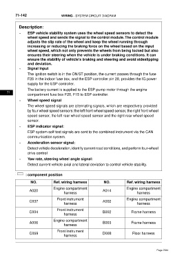
: component position
NO. Ref. wiring harness NO. Ref. wiring harness
Engine compartment Engine compartment
A020 A014
harness harness
Front instrument Engine compartment
C037 A002
harness harness
Front instrument
C004 B002 Frame harness
harness
Engine compartment
A006 B003 Frame harness
harness
Front instrument
C059 D008 Floor harness
harness
Page 2344