
Page 2347 - Foton Workshop Manual - Tunland (AT)
P. 2347
WIRING - SYSTEM CIRCUIT DIAGRAM 71-145
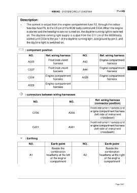
Description:
• The current is output from the engine compartment fuse F2, through the indoor
fuse box fuse F6, to the C5 pin of the BCM body control unit C034.When the engine
is started and the headlights are not turned on, the daytime running light is switched
on. The daytime running light supply is output from the C11 pin of the BCM body
control unit C034 to the pin 1 of the daytime running light, and ground by pin 2, and
the daytime light is switched on.
: component position
NO. Ref. wiring harness NO. Ref. wiring harness
Front instrument Engine compartment
A020 A43
harness harness
Front instrument Engine compartment 71
C037 A44
harness harness
Engine compartment Engine compartment
C034 A028
harness harness
Engine compartment
A029
harness
: connectors between wiring harnesses
Ref. wiring harness
NO. NO.
(connector position)
Front instrument harness and
engine compartment harness
C206 A306
(left side of instrument
crossbeam)
Front instrument harness and
engine compartment harness
C201 A301
(left side of instrument
crossbeam)
: Earthing
NO. Earth point NO. Earth point
Beside the Beside the
combination combination
A1 headlamp at the left A2 headlamp at the right
of the engine of the engine
compartment compartment
Page 2347