
Page 196 - Zoo Animal Learning and Training
P. 196
200 Section III: Spinal Procedures
the author as cranial as the T2–T3 disc space (after release of the canal, these limits are defined in each individual case based on the
scapulum and with internal rotation of the limb), and this com- location of the extruded/protruded disc material on advanced
pared favorably to the dorsal approach that is very deep at this level imaging. The surgeon must also keep in mind that the cranial and
(Pierre Moissonnier, personal observation). caudal attachments of the annulus fibrosus are located cranial and
At the level of the lumbar intumescence (L4–S1), particular care caudal to the vertebral endplates. Caudal to T10, the dorsal limit of
must be taken to identify the ventral branches of the spinal nerves the intervertebral foramina is approximately at the level of the
and protect them with a nerve retractor to avoid lower motor neu- accessory process (Figures 23.2 and 23.3). The spinal nerve is iden-
ron deficits. A transiliac approach to the L7–S1 intervertebral disc tified and a nerve retractor is positioned over the ventral branch
space was described to allow lateral corpectomy in this particular during lateral corpectomy (Figure 23.4). In some instances, this
location [28]. nerve can be transected (rhizotomy) to facilitate the surgical
Lateralization of the disc material within the canal on preopera- approach; this is not recommended caudal to L3.
tive imaging determines the side of the approach; when purely The slot is created perpendicular to the long axis of the spine.
ventral compression exists, a right‐handed surgeon is typically Patient positioning is particularly important in order to limit the
more comfortable with a left‐sided approach. risk of inadvertently entering the vertebral canal. The surgical burr
initially penetrates the cortical bone of the lateral aspect of the ver-
tebral body followed by cancellous bone (Figures 23.1 and 23.5).
Instrumentation Hemorrhage from the cancellous bone is controlled with bone wax
A general instrumentation pack, standard neurosurgical instru-
ments (e.g., Freer dissector‐elevator, Lempert rongeurs, Kerrison
rongeurs), and a high‐speed drill are necessary. Appropriate self‐
retaining retractors are essential to allow adequate exposure of the
surgical site.
Surgical Technique
In the preliminary description of the technique, the following theo-
retical landmarks were described. The slot should extend
(Figure 23.1):
• one‐quarter of the length of each vertebral body (craniocaudally);
• half the height of the vertebral body;
• half (50%) to two‐thirds (66%) of the vertebral canal diameter
width.
From a more practical point of view, and since extruded disc
material can migrate cranial and/or caudal within the vertebral
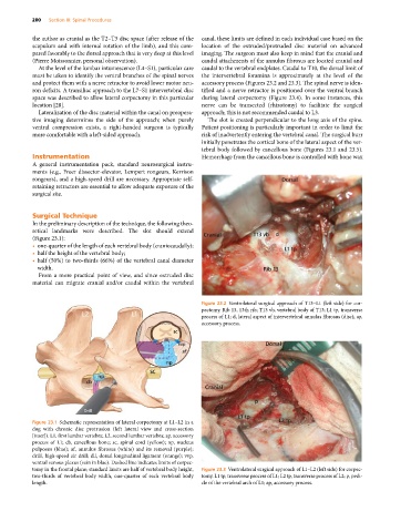
Figure 23.2 Ventrolateral surgical approach of T13–L1 (left side) for cor-
pectomy. Rib 13, 13th rib; T13 vb, vertebral body of T13; L1 tp, transverse
process of L1; d, lateral aspect of intervertebral annulus fibrosus (disc); ap,
accessory process.
Figure 23.1 Schematic representation of lateral corpectomy at L1–L2 in a
dog with chronic disc protrusion (left lateral view and cross‐section
[inset]). L1, first lumbar vertebra; L2, second lumbar vertebra; ap, accessory
process of L1; cb, cancellous bone; sc, spinal cord (yellow); np, nucleus
pulposus (blue); af, annulus fibrosus (white) and its removal (purple);
drill, high‐speed air drill; dll, dorsal longitudinal ligament (orange); vvp,
ventral venous plexus (vein in blue). Dashed line indicates limits of corpec-
tomy in the frontal plane; standard limits are half of vertebral body height, Figure 23.3 Ventrolateral surgical approach of L1–L2 (left side) for corpec-
two‐thirds of vertebral body width, one‐quarter of each vertebral body tomy. L1 tp, transverse process of L1; L2 tp, transverse process of L2; p, pedi-
length. cle of the vertebral arch of L1; ap, accessory process.