
Page 280 - Divyank Tyagi
P. 280
246 | ChaptEr 7 InteroperabIlIty: WorkIng MultIplatforM
7. Select all the perimeter walls—using the Tab key or Ctrl to add them individually to the
selection.
8. Select the Attach Top/Base tool from the Modify | Walls tab, set the Top option in the
Options bar, and pick the roof by face created in step 6.
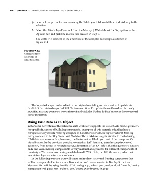
The walls will connect to the underside of the complex roof shape, as shown in
Figure 7.14.
Figure 7.14
Completed roof
with tops of
walls attached
The imported shape can be edited in the original modeling software and will update via
the link if the original exported SAT file is overwritten. To update the roof based on the newly
modified massing geometry, select the roof and click the Update To Face button in the contextual
tab of the ribbon.
Using CaD Data as an Object
Yet another derivation of the reference data workflow supports the use of CAD model geometry
for specific instances of building components. Examples of this scenario might include a
complex canopy structure being designed in SolidWorks or a building’s structural framing
being modeled in Bentley Structural Modeler. The workflow is again similar to that of using
CAD data as a mass or face; however, the file format will help you control the component’s
visualization. In the previous exercise, we used an SAT format to transfer complex curved
geometry from Rhino to Revit; however, a limitation of an SAT file is that the geometry contains
only one layer, making it impossible to vary material assignments for different components of
the design. We recommend using a solids-based DWG, DGN, or DXF file format, which will
maintain a layer structure in most cases.
In the following exercise, you will create an in-place structural framing component that
will act as a placeholder for a consultant’s structural model created in Bentley Structural
Modeler. You will be using the file c07-Framing.dgn, which you can download from the book’s
companion web page: www.sybex.com/go/masteringrevit2015.
c07.indd 246 5/3/2014 10:48:57 AM