
Page 326 - Parker - Parker Pneumatic
P. 326
PDE2600PNUK
Parker Pneumatic Origa OSP-E Electric Linear Actuators
Sizing Performance
Overview Performance Overview
Maximum Loadings Characteristics Unit Description
Series OSP-E25SB OSP-E32SB OSP-E50SB
Sizing of Actuator Pitch [mm] 5 5 10 5 10 25
The following steps are recommended for Max. speed [m/s] 0.25 0.25 0.5 0.25 0.5 1.25
selection : Linear motion per revolution [mm] 5 5 10 5 10 25
drive shaft
1. Recommended maximum Max. rpm, drive shaft [min 3 000 3 000 3 000
-1]
acceleration is shown in graphs
2. Required torque is shown in graphs Max. effective action force F [N] 250 600 1 500 3.1 7.3
A
Corresponding torque
0.35
1.7
0.75 1.3
[Nm]
3. Check that maximum values in the on drive shaft
adjacent charts are not exceeded. No-load torque [Nm] 0.2 0.2 0.3 0.3 0.4 0.5
4. When sizing and specifying the Max. allowable torque [Nm] 0.6 1.5 2.8 4.2 7.5 20
motor, the RMS-average torque on drive shaft
must be calculated using the cycle Repeatability [mm/m] ±0.05 ±0.05 ±0.05
time of the application. Max. Standard stroke length [mm] 1100 2000 3200
5. Check that the maximum allowable
unsupported length is not exceeded.
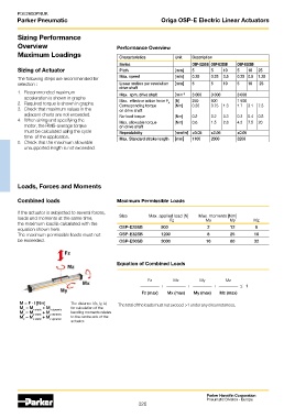
Loads, Forces and Moments
Combined loads Maximum Permissible Loads
If the actuator is subjected to several forces,
loads and moments at the same time, Size Max. applied load [N] Max. moments [Nm] Mz
My
Fz
Mx
the maximum load is calculated with the
equation shown here. OSP-E25SB 500 2 12 8
The maximum permissible loads must not OSP-E32SB 1200 8 25 16
be exceeded. OSP-E50SB 3000 16 80 32
Equation of Combined Loads
Fz Mx My Mz
+ + + ≤ 1
Fz (max) Mx (max) My (max) Mz (max)
M = F · l [Nm] The distance l (lx, ly, lz) The total of the loads must not exceed >1 under any circumstances.
M = M x static + M x dynamic for calculation of the
x
M = M y static + M y dynamic bending moments relates
y
M = M + M to the centre axis of the
z z static z dynamic
actuator.
Parker Hannifin Corporation
Pneumatic Division - Europe
326