
Page 11 - Tlahuizcalli CB-30_Neat
P. 11
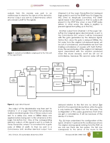
outputs  from  this  module  was  sent  to  an          Channel  2  of  the  Logic  Fan-in/Fan-Out  (delayed
          oscilloscope to visualize the signals of the detector.   logic pulse) is used as the START input to trigger the
          Another output was sent to a discriminator, which       TAC  (Time  to  Amplitude  Converter).  The  START
          sets a lower cutoff for the signals.                    signal needs to be delayed so that no pulse is still
                                                                  present  in the STOP line when a new START pulse
                                                                  arrives;  in  other  words,  the  delay  is  applied  to
                                                                  prevent signals from piling up in the TAC.
                                                                   Another output from Channel 1 of the Logic Fan-
                                                                  in/Fan-Out (original signal discriminated), is sent to
                                                                  the Coincidence Unit, where it will be compared
                                                                  with  the  gate  generated  by  the  delayed  signal.
                                                                  Notice that, since this gate is delayed 140    , the
                                                                  first pulse from the original not-delayed signal, will
                                                                  be out of coincidence, and therefore we won’t be
                                                                  making coincidence of a pulse with itself. Further-
                                                                  more, the second pulse of the original not-delayed
                                                                  signal  (associated  with  the  electron  produced
          Figure 1. Cylindrical Scintillator employed for the first part   when  the  muon  decays),  won’t  be  left  out  of
          of the experiment.                                      coincidence,  because  this  second  pulse  will  be


          Figure 2. Logic circuit layout.                         delayed  relative  to  the  first  one  by  about  2
                                                                  (which is the expected decay time), while the gate
           The output of the discriminator was then sent to       is  only  behind  by  140      from  the  first  pulse.  This
          Channel  1  of  a  Logic  Fan-in/Fan-Out  producing     configuration of the pulses guarantees that when
          multiple identical signals. One of those outputs was    we  get  a  coincidence,  it  will  be  because  of  the
          sent  to  a  delay  box,  were  a  140      delay  was   decay of a muon.
          applied before being sent to the Channel 2 of the
          Logic  Fan-in/Fan-Out.  One  of  the  corresponding      Fig. (3) helps understand the configuration of the
          identical outputs of this signal is sent to a Gate &    signal. Channel 1 (yellow) in the oscilloscope shows
          Delay Generator, where it is converted into a gate      the original analog signal coming from the PMT; as
          pulse  of  10      of  width,  to  then  be  sent  to  a   we  can  see  there  are  two  pulses,  the  first  one
          Coincidence  Unit.  Another  identical  output  from    corresponds  to  the  arrival  of  the  muon  to  the

                                                                                                            10
           Año 10 Núm. 30 septiembre-diciembre 2024                                    Tlahuizcalli ISSN: 2448-7260