
Page 57 - GuardII+ Series 4208 Platform EV User Manual
P. 57
User Instructions
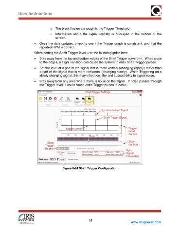
o The black line on the graph is the Trigger Threshold.
o Information about the signal stability is displayed in the bottom of the
screen.
• Once the data updates, check to see if the Trigger graph is consistent, and that the
reported RPM is correct.
When setting the Shaft Trigger level, use the following guidelines:
• Stay away from the top and bottom edges of the Shaft Trigger waveform. When close
to the edges, a slight variation can cause the system to miss Shaft Trigger pulses.
• Set the level at a part of the signal that is more vertical (changing rapidly) rather than
a part of the signal that is more horizontal (changing slowly). When Triggering on a
slowly changing signal, this may introduce jitter and susceptibility to signal noise.
• Stay away from any area where there is noise on the signal. If noise passes through
the Trigger level, it could cause extra Trigger pulses to occur.
Figure 6-24 Shaft Trigger Configuration
51
www.irispower.com