
Page 54 - GuardII+ Series 4208 Platform EV User Manual
P. 54
User Instructions
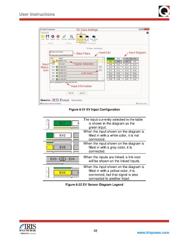
Figure 6-21 EV Input Configuration
The input currently selected in the table
is shown in the diagram as the
green input.
When the input shown on the diagram is
filled in with a white color, it is not
connected.
When the input shown on the diagram is
filled in with a grey color, it is
connected.
When the inputs are linked, a link icon
will be shown on the linked inputs.
When the input shown on the diagram is
filled in with a yellow color, it is
connected, but that signal is also
connected to another input.
Figure 6-22 EV Sensor Diagram Legend
48
www.irispower.com