
Page 53 - GuardII+ Series 4208 Platform EV User Manual
P. 53
User Instructions
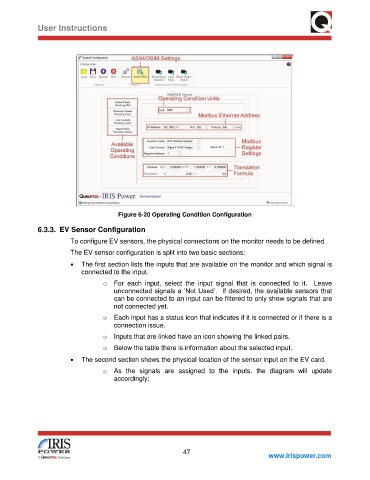
Figure 6-20 Operating Condition Configuration
6.3.3. EV Sensor Configuration
To configure EV sensors, the physical connections on the monitor needs to be defined.
The EV sensor configuration is split into two basic sections:
• The first section lists the inputs that are available on the monitor and which signal is
connected to the input.
o For each input, select the input signal that is connected to it. Leave
unconnected signals a ‘Not Used’. If desired, the available sensors that
can be connected to an input can be filtered to only show signals that are
not connected yet.
o Each input has a status icon that indicates if it is connected or if there is a
connection issue.
o Inputs that are linked have an icon showing the linked pairs.
o Below the table there is information about the selected input.
• The second section shows the physical location of the sensor input on the EV card.
o As the signals are assigned to the inputs, the diagram will update
accordingly:
47
www.irispower.com