
Page 441 - Kitab3DsMax
P. 441
Chapter 13: Modeling with Polygons and Patches
The Surface Properties rollout includes Flip and Unify buttons to control the direction of the normal vec-
tors. Flip reverses the direction of the normals of each selected face; Unify makes all normals face in the
same direction based on the majority. The Flip Normal Mode button activates a mode where you can click
individual faces and flip their normals. This mode stays active until you click the Flip Normal Mode button
again or right-click in the viewport.
Material IDs are used by the Multi/Sub-Object material type to apply different materials to different
patches within an object. By selecting a patch subobject, you can use this control to apply a unique mate-
rial to each patch.
Cross-Ref
You can find more information on the Multi/Sub-Object material type in Chapter 16, “Creating and Applying
Standard Materials.” n
You also can assign a patch to a unique Smoothing Group. To do this, select a patch and click a Smoothing
Group number.
Tutorial: Creating a maple leaf from patches
Because patches are a good modeling type for organic objects, let’s put it to the test by trying to create a
maple leaf. Because of the symmetry of the leaf, you really need to create only half of the leaf. You can then
use the Mirror tool to create the other half.
To model a maple leaf using patches, follow these steps:
1. Open the Maple leaf.max file from the Chap 13 directory on the DVD.
This file includes a background image of a real maple leaf loaded into the Front viewport.
2. Select Create ➪ Patch Grids ➪ Tri Patch, and drag in the Front viewport to create a square patch
grid from the base where the stem is to the upper-left interior area of the leaf. The right edge of
the patch should run about halfway up along the midline of the leaf.
3. In the Modify panel, right-click the Tri Patch name and select Convert to Editable Patch from the
pop-up menu.
4. In the Modifier Stack, select the Element subobject mode (or press the 4 key) and then select the
patch element. With the Propagate option selected, click the Subdivide button.
5. Select the Edge subobject mode (or press the 2 key), and select one of the edges that is completely
within the interior area of the background leaf image. Then press the Add Tri button to extend
the patch. Repeat this step until you have added a patch for each point around the outer perime-
ter of the leaf.
6. Select Vertex subobject mode (or press the 1 key). With the Select and Move button on the main
toolbar, select and drag the edge vertices so they align with the corners of the background leaf.
Move all internal vertices so they lie within the leaf area. Select each vertex that lies along the
outer edge of the leaf, and move its handles so the patch edge aligns with the background leaf’s
border. If the handles move together, hold down the Shift key to move them individually.
7. Deselect the Vertex subobject mode. In the Surface Properties rollout, enable all the options, and
set the Relax Value to 1.0 and the Iterations to 50. This smoothes out the wrinkles in the patch.
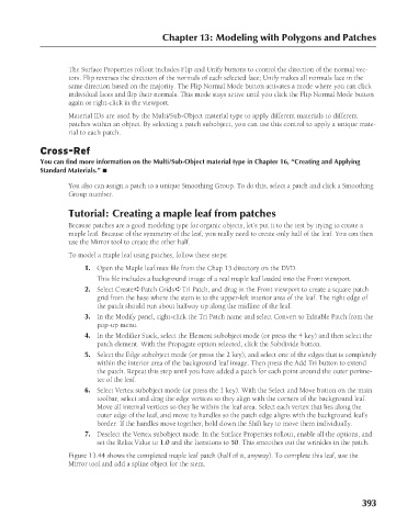
Figure 13.44 shows the completed maple leaf patch (half of it, anyway). To complete this leaf, use the
Mirror tool and add a spline object for the stem.
393
6/30/10 4:23 PM
20_617779-ch13.indd 393
20_617779-ch13.indd 393 6/30/10 4:23 PM