Page 521 - Kitab3DsMax
P. 521
Chapter 17: Adding Material Details with Maps


                           that the shape is a cylinder. The Shrink-Wrap Environment plasters the map directly on the scene as if it
                           were covering it like a blanket. All four corners of the bitmap are pulled together to the back of the
                           wrapped object. The Screen mapping type just projects the map flatly on the background.
                           The Show Map on Back option causes planar maps to project through the object and be rendered on the
                           object’s back.
                           The U and V coordinates define the X and Y positions for the map. For each coordinate, you can specify an
                           Offset value, which is the distance from the origin. The Tiling value is the number of times to repeat the
                           image and is used only if the Tile option is selected. If the Use Real-World Scale option is selected, then the
                           Offset fields change to Height and Width and the Tiling fields change to Size. The Mirror option inverts the
                           map. The UV, VW, and WU options apply the map onto different planes.
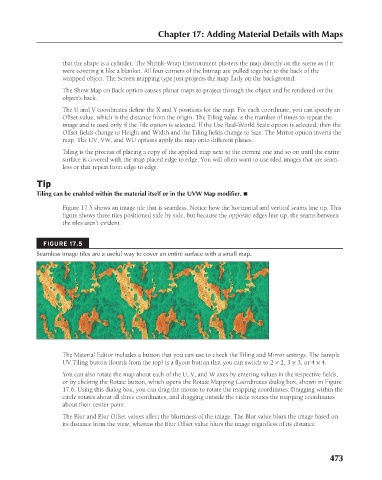
                           Tiling is the process of placing a copy of the applied map next to the current one and so on until the entire
                           surface is covered with the map placed edge to edge. You will often want to use tiled images that are seam-
                           less or that repeat from edge to edge.

                   Tip
                   Tiling can be enabled within the material itself or in the UVW Map modifier. n
                           Figure 17.5 shows an image tile that is seamless. Notice how the horizontal and vertical seams line up. This
                           figure shows three tiles positioned side by side, but because the opposite edges line up, the seams between
                           the tiles aren’t evident.


                     FIGURE 17.5
                   Seamless image tiles are a useful way to cover an entire surface with a small map.


                           The Material Editor includes a button that you can use to check the Tiling and Mirror settings. The Sample
                           UV Tiling button (fourth from the top) is a flyout button that you can switch to 2 × 2, 3 × 3, or 4 × 4.
                          You can also rotate the map about each of the U, V, and W axes by entering values in the respective fields,
                          or by clicking the Rotate button, which opens the Rotate Mapping Coordinates dialog box, shown in Figure
                          17.6. Using this dialog box, you can drag the mouse to rotate the mapping coordinates. Dragging within the
                          circle rotates about all three coordinates, and dragging outside the circle rotates the mapping coordinates
                          about their center point.
                          The Blur and Blur Offset values affect the blurriness of the image. The Blur value blurs the image based on
                          its distance from the view, whereas the Blur Offset value blurs the image regardless of its distance.


                                                                                                     473


                                                                                                         6/30/10   4:25 PM
           25_617779-ch17.indd   473
           25_617779-ch17.indd   473                                                                     6/30/10   4:25 PM

