
Page 182 - Workshop Manual - Aumark (BJ1051)
P. 182
04-38
Diagnose- ABS system
6-1 ABS Ring Gear Damaged (Right Front Wheel)
6-2 ABS Ring Gear Damaged (Left Front Wheel)
6-3 ABS Ring Gear Damaged (Right Rear Wheel)
6-4 ABS Ring Gear Damaged (Left Rear Wheel)
Tip:
Since the 4 ABS sensors use same control mode, the diagnostic procedure for ABS sensors of left
front, right rear, and left rear wheels is the same as that for the sensor of right front wheel.
Description:
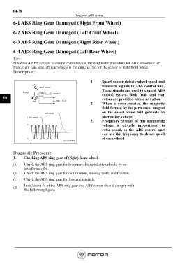
1. Speed sensor detects wheel speed and
transmits signals to ABS control unit.
speed sensor
These signals are used to control ABS
Rotor magnet control system. Both front and rear
04 coil rotors are provided with a serration.
to ABS
2. When a rotor rotates, the magnetic
field formed by the permanent magnet
on the speed sensor will generate an
low speed
High speed alternating voltage.
3. Frequency changes of this alternating
voltage is directly proportional to
rotor speed, so the ABS control unit
can use this frequency to detect speed
of each wheel.
Diagnostic Procedure
1. Checking ABS ring gear of (right) front wheel
(a) Check the ABS ring gear for looseness. Its installation should be an
interference fit.
(b) Check the ABS ring gear for deformation, missing teeth, and fracture.
(c) Check the ABS ring gear for foreign materials.
Installation fit of the ABS ring gear and ABS sensor should comply with
(d)
the following figure.
Page 182