Page 259 - Workshop Manual - Aumark (BJ1051)
P. 259

04-115
                                                       Diagnosis- illumination


               Diagnostic Procedure

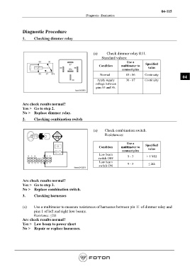
               1.     Checking dimmer relay


                                                           (a)       Check dimmer relay R11.
                                                                 Standard values:
                                                                                 Use a      Specified
                                                               Condition     multimeter to    value
                                                                              connect pins
                                                                Normal          85 - 86     Continuity
                                                                                                                   04
                                                              Apply supply      30 - 87     Continuity
                                                             voltage between
                                                             pins 85 and 86.


               Are check results normal?
               Yes >   Go to step 2.
               No >    Replace dimmer relay.

               2.     Checking combination switch

                                                           (a)     Check combination switch.
                                                                   Resistances:

                                                                                 Use a
                                                               Condition     multimeter to   Specified
                                                                                              value
                                                                              connect pins
                                                               Low beam
                                                               switch OFF        9 - 3       > 1 MΩ
                                                               Low beam          9 - 3        ≤ 2Ω
                                                               switch ON


               Are check results normal?
               Yes >   Go to step 3.
               No >    Replace combination switch.

               3.     Checking harnesses

               (a)     Use a multimeter to measure resistances of harnesses between pin 11 of dimmer relay and
                      pins 1 of left and right low beams.
                      Resistance: ≤2Ω
               Are check results normal?
               Yes >   Low beam to power short
               No >    Repair or replace harnesses.


                                                                                                         Page 259
   254   255   256   257   258   259   260   261   262   263   264