Page 730 - Workshop Manual - Aumark (BJ1051)
P. 730

25-20
                                             Rear axle- Differential assembly


          Inspection


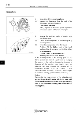
                                                    1.     Inspect the driven gear jumpiness
                                                    (a).    Measure the jumpiness from the back of the
                                                           driven gear with a dial indicator.
                                                           Limit value: 0.07 mm
                                                          If the jumpiness of the driven gear is beyond the
                                                           limit value, replace with a new driven gear.


                                                    2.     Inspect the meshing marks of driving gear
                                                           and driven gear
                                                    (a).    Check the meshing marks of the driven gear by
                                                           red lead powder.
                                                    (b).    Correct meshing marks of the driven gear
                                                           Position: At the higher part of the tooth
                                                           surface of the driven gear and slightly deflect
                                                           to the small end.
                                                           Length: ≥ 60% of the tooth surface
                                                           Width: ≥ 50% of the tooth surface
                                                    If the meshing marks of the driving gear and the
                                                    driven gear are not correct, adjust them by changing

   25                                               the number of the washers  through the increase or
                                                    decrease of the driving  gear bearing seat and
                                                    adjusting the nuts through the rotation of the
                                                    differential bearing. (Refer to “chapter 25 rear
                                                    axle-differential assembly, overhaul”, and “chapter
                                                    25 rear axle- driving gear assembly, overhaul”)
                                                    Notice:
                                                    Ensure that the ring number of the adjusting nuts
                                                    screwed in on the differential side is the same with
                                                    that screwed out to maintain the same pre-stressing
                                                    force of the differential bearing, and then fasten the
                                                    locking plates.


                                                                                                         Page 730
   725   726   727   728   729   730   731   732   733   734   735