
Page 123 - Fiber Optic Communications Fund
P. 123
104 Fiber Optic Communications
approaches zero as N → ∞. This is because sometimes the field component after a round trip may be positive
and sometimes it may be negative, and the net sum goes to zero if m is not an integer. When m is an integer,
the optical fields after each round trip add up coherently.
From Eq. (3.41), we see that only a discrete set of frequencies or wavelengths are supported by the cavity.
They are given by
2nL
= , m = 1, 2, … , (3.43)
m
m
or
mc
f = . (3.44)
m
2nL
These frequencies correspond to the longitudinal modes of the cavity, and can be changed by varying the
cavity length L. The laser frequency f must match one of the frequencies of the set f , m = 1, 2, … The
m
spacing Δf between longitudinal modes is constant,
c
Δf = f − f = . (3.45)
m m−1
2nL
The longitudinal spacing Δf is known as the free spectral range (FSR). In a two-level atomic system, the
gain would occur only for the frequency =(E − E )∕ℏ. However, in practical systems, these levels are
1
2
not sharp; each level is a broad collection of sublevels and, therefore, the gain would occur over a range of
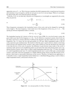
frequencies. Fig. 3.12 shows the loss and gain profiles of a FP laser. Many longitudinal modes of the FP
cavity experience gain simultaneously. The mode for which the gain is equal to the loss (shown as the lasing
mode) becomes the dominant mode. In theory, other modes should not reach the threshold since their gain
is less than the loss of the cavity. In practice, the difference in gain between many modes of the cavity is
extremely small, and one or two neighboring modes on each side of the main mode (lasing mode) carry a sig-
nificant fraction of power. Such a laser is called a multi-longitudinal-mode laser. Fig. 3.13 shows the output
of a multi-longitudinal-mode laser. If a multi-longitudinal-mode laser is used in fiber-optic communication
systems, each mode of the laser propagates at a slightly different group velocity in the fiber because of dis-
persion, which leads to intersymbol interference at the receiver. Therefore, for high-bit-rate applications, it
is desirable to have a single-longitudinal-mode (SLM) laser. A distributed Bragg grating is used to obtain a
single longitudinal mode, as discussed in Section 3.8.5.
Gain coefficient
Cavity loss
Longitudinal Lasing mode
α cav
modes
Frequency, f
c/2nL
Figure 3.12 Loss and gain profiles of a Fabry–Perot laser.