
Page 1048 - 2006 HARLEY FLSTCI SERVICE MANUAL
P. 1048
8.5 8-9
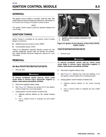
Ignition control module connector [10] Figure 8-6. Ignition Control Module: All But FXST, FXSTB, FXSTS, FXSTD 1WARNING 1WARNING prevent accidental vehicle start-up, which could cause death or serious injury, disconnect negative (-) See Figure 8-7. Remove two nuts and washers (1) to free ignition control module from mounting bracket. Unplug ignition control module connector [10]. Depress external latches on the socket housing Use a rocking motion to separate pin and socket
2 2006 Softail: Electrical
1 battery cable before proceeding. (00048a) Disconnect negative battery cable.
2 Screw (2) FXST/FXSTB/FXSTS/FXSTD Remove seat. side. halves.
10392 1. 2. 1. To 2. 3. 4. a. b.
IGNITION CONTROL MODULE The ignition control module is mounted under the seat. See Softail Models Electrical Diagnostic Manual for information on the function and testing of the ignition control module. NOTE The ignition control module cannot be repaired. Replace the Ignition timing is controlled by the ignition control module Manifold absolute pressure sensor (MAP). There is no adjustment required. Should a sensor fail, the resulting diagnostic trouble code will identify the problem. See Softail Models Electrical Diagnostic Manual for more All But FXST/FXSTB/FXSTS/FXSTD 1WARNING 1WARNING prevent accidental vehicle start-up, which could ca
GENERAL unit if it fails. IGNITION TIMING based on input from: Crank position sensor (CKP). REMOVAL Remove seat. side. halves.
HOME ● ● information. 1. To 2. 3. 4. a. b.