
Page 1049 - 2006 HARLEY FLSTCI SERVICE MANUAL
P. 1049
4
1
3
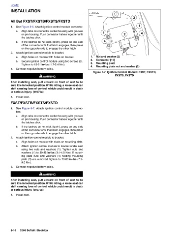
2 Figure 8-7. Ignition Control Module: FXST, FXSTB, FXSTS, FXSTD
Mounting plate nut and washer (2)
4 Nut and washer (2) Connector [10] Mounting plate
1
d0741x8x 1. 2. 3. 4.
INSTALLATION All But FXST/FXSTB/FXSTS/FXSTD See Figure 8-6. Attach ignition control module connector. Align tabs on connector socket housing with grooves on pin housing. Push connector halves together until the latches click. If the latches do not click (latch), press on one side of the connector until that latch engages, then press on the opposite side to engage the other latch. Attach ignition control module to bracket. Align holes on module with holes on bracket. Secure ignition control module using two screws (3). Tighten to 15-21 in-lbs (1.7-2.4 Nm). Connect negative battery cable. 1WARNING 1WARNING After installing seat, pull upward on front
HOME 1. a. b. 2. a. b. 3. 4. 1. tors. a. b. 2. a. b. 3. 4. 8-10