
Page 1073 - 2006 HARLEY FLSTCI SERVICE MANUAL
P. 1073
4 CAVITY 1 2 1 2 1 2 3 4 1 2 3 4 5 6
3
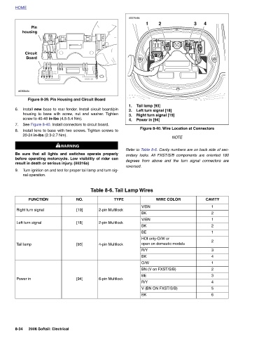
2 Right turn signal [19] Figure 8-40. Wire Location at Connectors NOTE Refer to Table 8-6. Cavity numbers are on back side of sec- ondary locks. All FXST/S/B components are oriented 180 degrees from above and the turn signal connectors are WIRE COLOR HDI only-O/W or open on domestic models BN (V on FXST/S/B) V (BN ON FXST/S/B)
Tail lamp [93] Left turn signal [18] Power in [94]
Table 8-6. Tail Lamp Wires TYPE 2-pin Multilock 2-pin Multilock 4-pin Multilock 6-pin Multilock
1 V/BN BK V/BN BK BE R/Y BK O/W BE R/Y BK
d0076x8x 1. 2. 3. 4. reversed.
68830-98 NO. [19] [18] [93] [94]
screw to 40-48 in-lbs (4.5-5.4 Nm). 20-24 in-lbs (2.3-2.7 Nm). result in death or serious injury. (00316a) 2006 Softail: Electrical
H-D USA Figure 8-39. Pin Housing and Circuit Board Install new base to rear fender. Install circuit board/pin housing to base with screw, nut and washer. Tighten See Figure 8-40. Install connectors to circuit board. Install lens to base with two screws. Tighten screws to 1WARNING 1WARNING Be sure that all lights and switches operate properly before operating motorcycle. Low visibility of rider can Turn ignition on and test for proper tail lamp and turn sig-
Pin housing Circuit Board nal operation. FUNCTION Right turn signal Left turn signal
HOME d0308x8x 6. 7. 8. 9. Tail lamp Power in 8-34