
Page 828 - 2006 HARLEY FLSTCI SERVICE MANUAL
P. 828
d0132x3x 3-41
1 2006 Softail: Engine
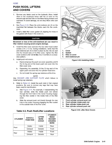
Figure 3-43. Installing Lifters 3 Front cylinder exhaust push rod Front cylinder intake push rod Rear cylinder intake push rod Rear cylinder exhaust push rod Figure 3-44. Lifter Bore Covers
4 2
2 Ribs on cover Anti-rotational pin 4
Cover Gasket
3
1
10604
1. 2. 3. 4. 1. 2. 3. 4.
which follows to CYLINDER HEAD/ LIFTER ROCKER BORE HOUSING COVER BORE Rear Inside Front Outside Front Inside Rear Outside
PUSH RODS, LIFTERS AND COVERS Remove any labels used on the hydraulic lifters. Install lifters in the crankcase bores with the oil hole on the inboard side and the flats on the lifters facing forward and rearward. To avoid damage, do not drop lifters onto cam See Figure 3-43. Place the anti-rotational pin (4) on the machined flat between the blocks cast into the crank- Install a new lifter cover gasket (2) aligning the holes in the gasket with those in the cover (1). CAUTION Movement or loss of the anti-rotational pin can result in lifter rotation causing severe engine damage. Install the lifter cover and start the four allen head socket screws (1/4
HOME 1. lobes. 2. case. 3. 4. wise pattern. 5. a. b. c. See 6. b. CYLINDER Front Rear