
Page 149 - GIGABYTE Service Manual-v3.0-110101
P. 149
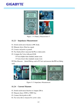
Figure 11-4: Battery Measurement-2


                   11.2.3  Impedance Measurement


                   01. Switch multi-meter function to    Diode.
                   02. Measure object: Data bus signal.
                   03. Connect red probe to ground.

                   04. Use black probe to measure the Pin or check point.
                   05. Compare the Value with good M/B:
                        - If Value higher than standard, means open.

                        - If Value lowers than standard, means short.
                   PCI Bus Measure:   (Install Debug card to PCI slot and measure the PIN on Debug
                   card)


                                          Figure 11-5: Impedance Measurement


                   11.2.4  Current Measure


                   01. Switch multi-meter function to Ampere 200 m
                   02. Measure object: DDR or DDR2 bus
                   03. Connect black probe to JP2

                   04. Use red probe to measure the current value.


                                                           127