
Page 92 - GIGABYTE Service Manual-v3.0-110101
P. 92
Example: Intel
X48-DQ6 identified by:
01. Post code C1-96-C1, C1-7F-C1.
02. ML-IP LC7 broken
03. For PCI-Express interface, the data output side must by pass 0.1U capacitor.
Therefore, impedance measure for this signal must check the both side components.
Signal Explanation:
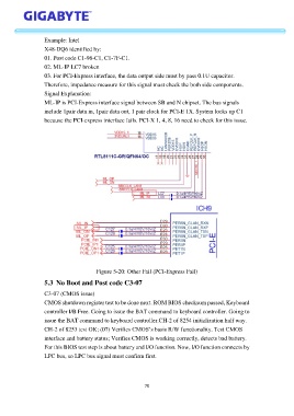
ML-IP is PCI-Express interface signal between SB and N chipset. The bus signals
include 1pair data in, 1pair data out, 1 pair clock for PCI-E 1X. System locks up C1
because the PCI-express interface fails. PCI-X 1, 4, 8, 16 need to check for this issue.
Figure 5-20: Other Fail (PCI-Express Fail)
5.3 No Boot and Post code C3-07
C3-07 (CMOS issue)
CMOS shutdown register test to be done next. ROM BIOS checksum passed, Keyboard
controller I/B Free. Going to issue the BAT command to keyboard controller. Going to
issue the BAT command to keyboard controller.CH-2 of 8254 initialization half way.
CH-2 of 8253 test OK; (07) Verifies CMOS’s basis R/W functionality. Test CMOS
interface and battery status; Verifies CMOS is working correctly, detects bad battery.
For this BIOS test step is about battery and I/O function. Now, I/O function connects by
LPC bus, so LPC bus signal must confirm first.
70