
Page 210 - FreesStyler® Installation and Startup
P. 210
®
INSTALLATION AND STARTUP
Chapter 10 Initial Startup
Startup Procedure
SCC
11) Check all inputs. To Check a Photo-Eye:
When the beam is blocked, the oval on the HMI is empty (clear).
a) Enter Door Photo-Eye When the beam is not blocked, the oval is filled (black).
b) All other installed Photo-Eyes
c) Enter Load Sensor (Entrance Treadle Door)
d) Exit load sensor (Exit Treadle Door)
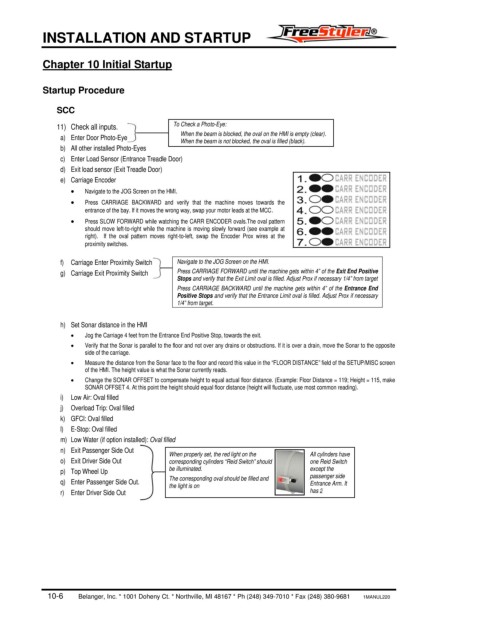
e) Carriage Encoder
• Navigate to the JOG Screen on the HMI.
• Press CARRIAGE BACKWARD and verify that the machine moves towards the
entrance of the bay. If it moves the wrong way, swap your motor leads at the MCC.
• Press SLOW FORWARD while watching the CARR ENCODER ovals.The oval pattern
should move left-to-right while the machine is moving slowly forward (see example at
right). If the oval pattern moves right-to-left, swap the Encoder Prox wires at the
proximity switches.
f) Carriage Enter Proximity Switch Navigate to the JOG Screen on the HMI.
g) Carriage Exit Proximity Switch Press CARRIAGE FORWARD until the machine gets within 4” of the Exit End Positive
Stops and verify that the Exit Limit oval is filled. Adjust Prox if necessary 1/4” from target
Press CARRIAGE BACKWARD until the machine gets within 4” of the Entrance End
Positive Stops and verify that the Entrance Limit oval is filled. Adjust Prox if necessary
1/4” from target.
h) Set Sonar distance in the HMI
• Jog the Carriage 4 feet from the Entrance End Positive Stop, towards the exit.
• Verify that the Sonar is parallel to the floor and not over any drains or obstructions. If it is over a drain, move the Sonar to the opposite
side of the carriage.
• Measure the distance from the Sonar face to the floor and record this value in the “FLOOR DISTANCE” field of the SETUP/MISC screen
of the HMI. The height value is what the Sonar currently reads.
• Change the SONAR OFFSET to compensate height to equal actual floor distance. (Example: Floor Distance = 119; Height = 115, make
SONAR OFFSET 4. At this point the height should equal floor distance (height will fluctuate, use most common reading).
i) Low Air: Oval filled
j) Overload Trip: Oval filled
k) GFCI: Oval filled
l) E-Stop: Oval filled
m) Low Water (if option installed): Oval filled
n) Exit Passenger Side Out When properly set, the red light on the All cylinders have
o) Exit Driver Side Out corresponding cylinders “Reid Switch” should one Reid Switch
p) Top Wheel Up be illuminated. except the
The corresponding oval should be filled and passenger side
q) Enter Passenger Side Out. the light is on Entrance Arm. It
r) Enter Driver Side Out has 2
10-6 Belanger, Inc. * 1001 Doheny Ct. * Northville, MI 48167 * Ph (248) 349-7010 * Fax (248) 380-9681 1MANUL220