Page 56 - FreesStyler® Installation and Startup
P. 56

®
            INSTALLATION AND STARTUP


            Chapter 4 Frame and Carriage Assembly


            Standard “Channel” Boom Installation

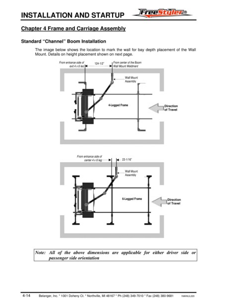
                   The image below shows the location to mark the wall for bay depth placement of the Wall
                   Mount. Details on height placement shown on next page.

                               From entrance side of   124-1/2”   From center of the Boom
                                     exit 4 x 6 leg        Wall Mount Weldment

                                                                 Wall Mount
                                                                 Assembly


                                                         4-Legged Frame               Direction
                                                                                      of Travel


                                         From entrance side of
                                            center 4 x 6 leg    23-1/16”

                                                                 Wall Mount
                                                                 Assembly


                                                                6-Legged Frame         Direction
                                                                                       of Travel


                   Note:  All of the above dimensions are applicable for either driver side or
                          passenger side orientation


            4-14        Belanger, Inc. * 1001 Doheny Ct. * Northville, MI 48167 * Ph (248) 349-7010 * Fax (248) 380-9681       1MANUL220
   51   52   53   54   55   56   57   58   59   60   61