
Page 16 - DuraBlaster® Wheel Cleaner
P. 16
®
DURABLASTER WHEEL CLEANER
Specifications
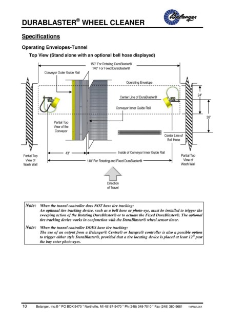
Operating Envelopes-Tunnel
Top View (Stand alone with an optional bell hose displayed)
150” For Rotating DuraBlaster®
140” For Fixed DuraBlaster®
Conveyor Outer Guide Rail
Operating Envelope
Center Line of DuraBlaster® 24”
Conveyor Inner Guide Rail
36”
Partial Top TY
View of the P
Conveyor
Center Line of
Bell Hose
43” Inside of Conveyor Inner Guide Rail
Partial Top Partial Top
View of 140” For Rotating and Fixed DuraBlaster® View of
Wash Wall Wash Wall
Direction
of Travel
Note: When the tunnel controller does NOT have tire tracking:
An optional tire tracking device, such as a bell hose or photo-eye, must be installed to trigger the
sweeping action of the Rotating DuraBlaster® or to actuate the Fixed DuraBlaster®. The optional
tire tracking device works in conjunction with the DuraBlaster® wheel sensor timer.
Note: When the tunnel controller DOES have tire tracking:
The use of an output from a Belanger® Centra® or Integra® controller is also a possible option
to trigger either style DuraBlaster®, provided that a tire locating device is placed at least 12” past
the bay enter photo-eyes.
10 Belanger, Inc.® * PO BOX 5470 * Northville, MI 48167-5470 * Ph (248) 349-7010 * Fax (248) 380-9681 1MANUL054