
Page 21 - DuraBlaster® Wheel Cleaner
P. 21
®
DURABLASTER WHEEL CLEANER
Installation
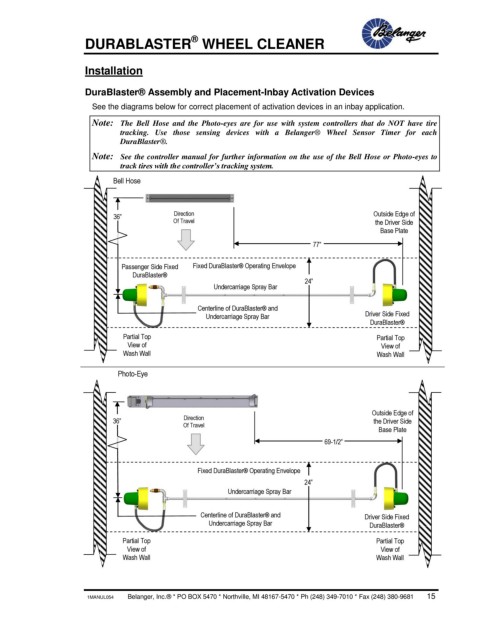
DuraBlaster® Assembly and Placement-Inbay Activation Devices
See the diagrams below for correct placement of activation devices in an inbay application.
Note: The Bell Hose and the Photo-eyes are for use with system controllers that do NOT have tire
tracking. Use those sensing devices with a Belanger® Wheel Sensor Timer for each
DuraBlaster®.
Note: See the controller manual for further information on the use of the Bell Hose or Photo-eyes to
track tires with the controller’s tracking system.
Bell Hose
36” Direction Outside Edge of
Of Travel the Driver Side
Base Plate
77”
Mini
mu
Passenger Side Fixed Fixed DuraBlaster® Operating Envelope m
DuraBlaster®
24”
Undercarriage Spray Bar
Centerline of DuraBlaster® and
Undercarriage Spray Bar Driver Side Fixed
DuraBlaster®
Partial Top Partial Top
View of View of
Wash Wall Wash Wall
Photo-Eye
Outside Edge of
36” Direction the Driver Side
Of Travel Base Plate
69-1/2”
Minimu
m
Fixed DuraBlaster® Operating Envelope
24”
Undercarriage Spray Bar
Centerline of DuraBlaster® and Driver Side Fixed
Undercarriage Spray Bar
DuraBlaster®
Partial Top Partial Top
View of View of
Wash Wall Wash Wall
1MANUL054 Belanger, Inc.® * PO BOX 5470 * Northville, MI 48167-5470 * Ph (248) 349-7010 * Fax (248) 380-9681 15