
Page 22 - DuraBlaster® Wheel Cleaner
P. 22
®
DURABLASTER WHEEL CLEANER
Installation
Utility Connections
Connect the air panel (Rotating DuraBlaster® ONLY) and optional DuraFlo™ pump to the
DuraBlaster® assemblies per the following instructions.
AIR PANEL (Rotating DuraBlaster® ONLY):
Mount the air panel.
Connect a 3/8” poly-tube airline from a clean, dry air supply to the regulator on the
DuraBlaster® air panel.
Connect a 1/4” black and a 1/4” grey air line from the valve on the air panel then tee off to
each DuraBlaster® assembly. Connect a black line from the tee to the black line out of each
DuraBlaster® and a gray line from the tee to the gray line coming out of each DuraBlaster®.
Try to keep the lines to each DuraBlaster® assembly close to equal length.
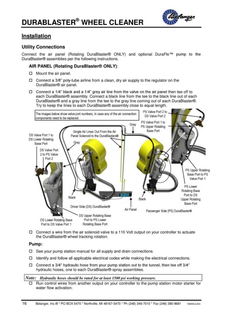
The images below show valve port numbers, in case any of the air connection PS Valve Port 2 to
DS Valve Port 2
components need to be replaced.
Gray PS Valve Port 1 to
PS Upper Rotating
Single Air Lines Out From the Air Base Port
DS Valve Port 1 to Panel Solenoid to the DuraBlasters®
DS Lower Rotating
Base Port Gray
DS Valve Port
2 to PS Valve
Port 2
PS Upper Rotating
Base Port to PS
Valve Port 1
PS Lower
Rotating Base
Port to DS
Black Black Upper Rotating
Base Port
Driver Side (DS) DuraBlaster®
Air Panel Passenger Side (PS) DuraBlaster®
DS Upper Rotating Base
DS Lower Rotating Base Port to PS Lower
Port to DS Valve Port 1 Rotating Base Port
Connect a wire from the air solenoid valve to a 110 Volt output on your controller to actuate
the DuraBlaster® wheel tracking rotation.
Pump:
See your pump station manual for all supply and drain connections.
Identify and follow all applicable electrical codes while making the electrical connections.
Connect a 3/4” hydraulic hose from your pump station out to the tunnel, then tee off 3/4”
hydraulic hoses, one to each DuraBlaster® spray assemblies.
Note: Hydraulic hoses should be rated for at least 1500 psi working pressure.
Run control wires from another output on your controller to the pump station motor starter for
water flow activation.
16 Belanger, Inc.® * PO BOX 5470 * Northville, MI 48167-5470 * Ph (248) 349-7010 * Fax (248) 380-9681 1MANUL054