
Page 20 - DuraBlaster® Wheel Cleaner
P. 20
®
DURABLASTER WHEEL CLEANER
Installation
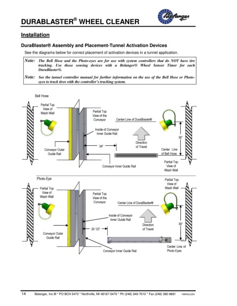
DuraBlaster® Assembly and Placement-Tunnel Activation Devices
See the diagrams below for correct placement of activation devices in a tunnel application.
Note: The Bell Hose and the Photo-eyes are for use with system controllers that do NOT have tire
tracking. Use those sensing devices with a Belanger® Wheel Sensor Timer for each
DuraBlaster®.
Note: See the tunnel controller manual for further information on the use of the Bell Hose or Photo-
eyes to track tires with the controller’s tracking system.
Bell Hose
Partial Top
View of
Wash Wall Partial Top
View of the
Conveyor Center Line of DuraBlaster®
Inside of Conveyor
Inner Guide Rail
36”
Direction TY
34” of Travel P
Conveyor Outer Center Line
Guide Rail of Bell Hose
Partial Top
Conveyor Inner Guide Rail View of
Wash Wall
Photo-Eye Partial Top
View of
Partial Top Wash Wall
View of Partial Top
Wash Wall View of the
Conveyor Center Line of DuraBlaster®
Inside of Conveyor
Inner Guide Rail
Direction 36”
Conveyor Outer 26 1/2” of Travel TY
P
Guide Rail
Center Line of
Conveyor Inner Guide Rail Photo Eyes
14 Belanger, Inc.® * PO BOX 5470 * Northville, MI 48167-5470 * Ph (248) 349-7010 * Fax (248) 380-9681 1MANUL054