
Page 31 - Gyro Wrap™
P. 31
™
GYRO WRAP
Installation
Utilities
General
The control relay function on the CCU to the MAC 4-Way Valve should be wired normally open. When
there is no vehicle at the Gyro-Wrap™, the solenoid valve is off (open), and line pressure is fed to the back
of the boom cylinders thus retracting both booms.
Before a vehicle reaches the Gyro-Wrap™, the control relay should energize the solenoid valve, sending
20 PSI of regulated air to the front of the cylinders, bringing in both booms to the vehicle.
Note: 20 PSI is a good starting point with a wheel speed of 72 to 80 RPM.
Air pressure can be adjusted for more or less penetration.
1) Flow controls on each cylinder needs to be adjusted to control speed at which booms move in and
out.
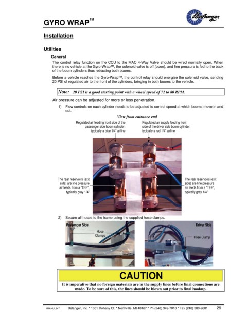
View from entrance end
Regulated air feeding front side of the Regulated air supply feeding front
passenger side boom cylinder, side of the driver side boom cylinder,
typically a blue 1/4” airline typically a red 1/4” airline
The rear reservoirs (exit The rear reservoirs (exit
side) are line pressure side) are line pressure
air feeds from a “TEE”, air feeds from a “TEE”,
typically gray 1/4” typically gray 1/4”
2) Secure all hoses to the frame using the supplied hose clamps.
Passenger Side Driver Side
Hose
Clamps Hose Clamp
CAUTION
It is imperative that no foreign materials are in the supply lines before final connections are
made. To be sure of this, the lines should be blown out prior to final hookup.
1MANUL247 Belanger, Inc. * 1001 Doheny Ct. * Northville, MI 48167 * Ph (248) 349-7010 * Fax (248) 380-9681 29