
Page 33 - Gyro Wrap™
P. 33
™
GYRO WRAP
Installation
Utilities
Pneumatics
The following section will explain the connection of the pneumatic lines to the oil reservoir.
Note: Early models of the “Pro Class” 80 and 100 systems use pneumatic valves and regulators
on the CCU. Refer to their system manual for connections.
The air panel can be mounted in the tunnel or the “back room”. The preferred location is the “back room”.
Pneumatic (Air) Panel
1) Locate supplied air panel and supply controlled 110VAC from relay of CCU to the MAC Valve.
2) Supply 120PSI maximum pneumatic line pressure from CCU or other clean, dry air supply to the
main air in feed.
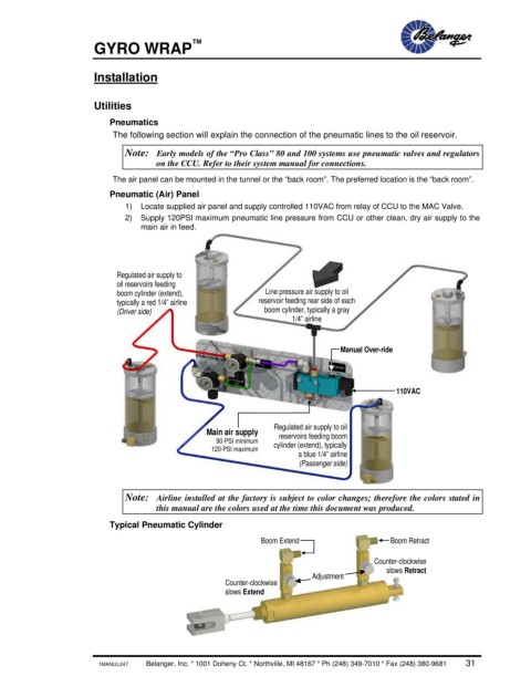
Regulated air supply to
oil reservoirs feeding
boom cylinder (extend), Line pressure air supply to oil
typically a red 1/4” airline reservoir feeding rear side of each
(Driver side) boom cylinder, typically a gray
1/4” airline
Manual Over-ride
110VAC
Regulated air supply to oil
Main air supply reservoirs feeding boom
90-PSI minimum cylinder (extend), typically
120-PSI maximum
a blue 1/4” airline
(Passenger side)
Note: Airline installed at the factory is subject to color changes; therefore the colors stated in
this manual are the colors used at the time this document was produced.
Typical Pneumatic Cylinder
Boom Extend Boom Retract
Counter-clockwise
slows Retract
Adjustment
Counter-clockwise
slows Extend
1MANUL247 Belanger, Inc. * 1001 Doheny Ct. * Northville, MI 48167 * Ph (248) 349-7010 * Fax (248) 380-9681 31