
Page 35 - Gyro Wrap™
P. 35
™
GYRO WRAP
Installation
Utilities
Hydraulic Drive Overview
This section will explain the installation of the hydraulic connections.
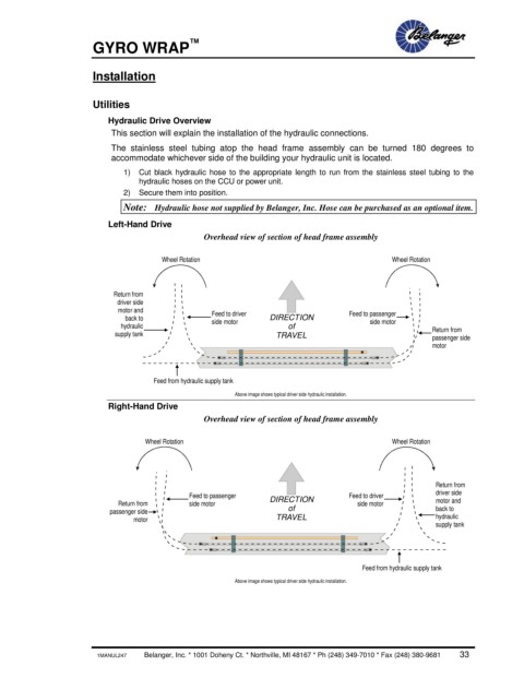
The stainless steel tubing atop the head frame assembly can be turned 180 degrees to
accommodate whichever side of the building your hydraulic unit is located.
1) Cut black hydraulic hose to the appropriate length to run from the stainless steel tubing to the
hydraulic hoses on the CCU or power unit.
2) Secure them into position.
Note: Hydraulic hose not supplied by Belanger, Inc. Hose can be purchased as an optional item.
Left-Hand Drive
Overhead view of section of head frame assembly
Wheel Rotation Wheel Rotation
Return from
driver side
motor and Feed to driver Feed to passenger
back to side motor DIRECTION side motor
hydraulic of Return from
supply tank TRAVEL passenger side
motor
Feed from hydraulic supply tank
Above image shows typical driver side hydraulic installation.
Right-Hand Drive
Overhead view of section of head frame assembly
Wheel Rotation Wheel Rotation
Return from
Feed to passenger DIRECTION Feed to driver driver side
Return from side motor side motor motor and
passenger side of back to
motor TRAVEL hydraulic
supply tank
Feed from hydraulic supply tank
Above image shows typical driver side hydraulic installation.
1MANUL247 Belanger, Inc. * 1001 Doheny Ct. * Northville, MI 48167 * Ph (248) 349-7010 * Fax (248) 380-9681 33