
Page 20 - DuraJet™ / AlumaJet™ Arches
P. 20
DURAJET™ ARCH
Installation
Arch Assembly
4. Place the arch in the tunnel so that the outside of the driver side base plate is 54-1/2 inches
off the inside guide rail of the conveyor. See the image below.
Partial Top View of Wash Wall
Top View of Inside Guide Rail 54-1/2”
DuraJet™ Arch of the Conveyor
Partial Top View
of Conveyor Driver Side
Base Plate
Direction
Of Travel Partial Top View of Wash Wall
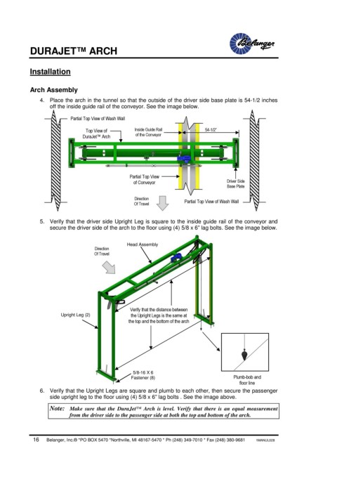
5. Verify that the driver side Upright Leg is square to the inside guide rail of the conveyor and
secure the driver side of the arch to the floor using (4) 5/8 x 6” lag bolts. See the image below.
Head Assembly
Direction
Of Travel
Verify that the distance between
Upright Leg (2) the Upright Legs is the same at
the top and the bottom of the arch
5/8-16 X 6
Fastener (8) Plumb-bob and
floor line
6. Verify that the Upright Legs are square and plumb to each other, then secure the passenger
side upright leg to the floor using (4) 5/8 x 6” lag bolts . See the image above.
Note: Make sure that the DuraJet™ Arch is level. Verify that there is an equal measurement
from the driver side to the passenger side at both the top and bottom of the arch.
16 Belanger, Inc.® *PO BOX 5470 *Northville, MI 48167-5470 * Ph (248) 349-7010 * Fax (248) 380-9681 1MANUL028