
Page 21 - DuraJet™ / AlumaJet™ Arches
P. 21
DURAJET™ ARCH
Installation
Arch Assembly
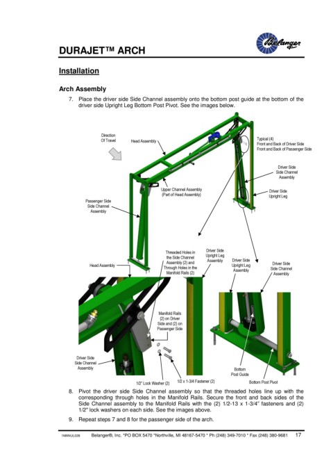
7. Place the driver side Side Channel assembly onto the bottom post guide at the bottom of the
driver side Upright Leg Bottom Post Pivot. See the images below.
Direction
Of Travel Head Assembly Typical (4)
Front and Back of Driver Side
Front and Back of Passenger Side
Driver Side
Side Channel
Assembly
Upper Channel Assembly Driver Side
(Part of Head Assembly) Upright Leg
Passenger Side
Side Channel
Assembly
Threaded Holes in Driver Side
the Side Channel Upright Leg Driver Side
Assembly
Head Assembly Assembly (2) and Upright Leg Driver Side
Through Holes in the Side Channel
Manifold Rails (2) Assembly Assembly
Manifold Rails
(2) on Driver
Side and (2) on
Passenger Side
Driver Side
Side Channel
Assembly Bottom
Post Guide
1/2” Lock Washer (2) 1/2 x 1-3/4 Fastener (2) Bottom Post Pivot
8. Pivot the driver side Side Channel assembly so that the threaded holes line up with the
corresponding through holes in the Manifold Rails. Secure the front and back sides of the
Side Channel assembly to the Manifold Rails with the (2) 1/2-13 x 1-3/4” fasteners and (2)
1/2" lock washers on each side. See the images above.
9. Repeat steps 7 and 8 for the passenger side of the arch.
1MANUL028 Belanger®, Inc. *PO BOX 5470 *Northville, MI 48167-5470 * Ph (248) 349-7010 * Fax (248) 380-9681 17