
Page 25 - DuraJet™ / AlumaJet™ Arches
P. 25
DURAJET™ ARCH
Installation
Utility Connections
Electrical
Motor Starter Panel
The DuraJet™ or AlumaJet™ Arch requires a 1/3 hp motor to drive the sweeping motion.
3-Phase wiring is required from a Motor Starter Panel to the 1/3 hp motor, located on the
Head assembly.
If the Motor Starter is purchased from Belanger®, it has 2 optional configurations:
· On an optional stand-alone panel
· Included as an optional part of the system controller
Note: If the optional motor starter panel IS purchased from Belanger®, it is supplied configured
specifically for your application.
Note: If the optional motor starter panel is NOT purchased from Belanger®, the motor starter
may be supplied in the field by the distributor or customer.
Note: A 120VAC output from the controller is required to operate the motor.
LED Option
The DuraJet™ includes LED-illuminated spray manifolds. The LED lights are bright white and
backlight the plastic manifold covers.
Note: The DuraJet™ LED lighting is wired in series with the 1/3 hp motor starter.
Note: The DuraJet™ LED lighting utilizes the same output as the motor starter panel.
Note: The DuraJet™ LED lighting also requires a 5 amp power supply enclosure.
Note: The DuraJet™ LED lighting includes an additional option for the lighting to flash.
Note: See Motor Starter Panel, above.
Utility Connections
Water
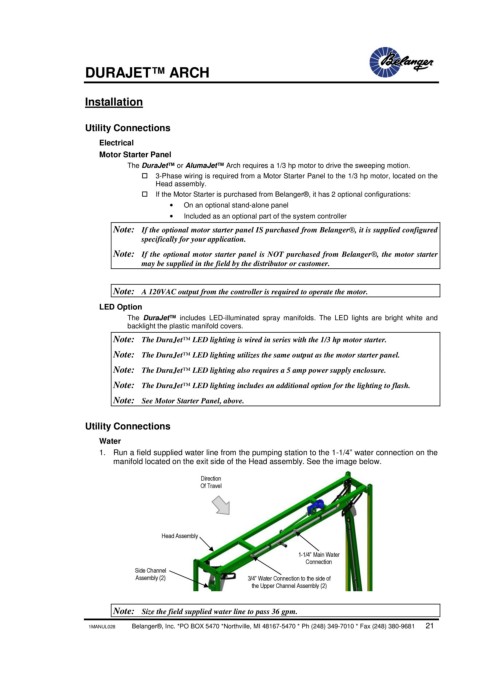
1. Run a field supplied water line from the pumping station to the 1-1/4” water connection on the
manifold located on the exit side of the Head assembly. See the image below.
Direction
Of Travel
Head Assembly
1-1/4” Main Water
Connection
Side Channel
Assembly (2) 3/4” Water Connection to the side of
the Upper Channel Assembly (2)
Note: Size the field supplied water line to pass 36 gpm.
1MANUL028 Belanger®, Inc. *PO BOX 5470 *Northville, MI 48167-5470 * Ph (248) 349-7010 * Fax (248) 380-9681 21