
Page 23 - DuraJet™ / AlumaJet™ Arches
P. 23
DURAJET™ ARCH
Installation
Arch Assembly
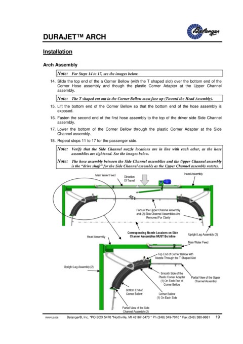
Note: For Steps 14 to 17, see the images below.
14. Slide the top end of the a Corner Bellow (with the T shaped slot) over the bottom end of the
Corner Hose assembly and though the plastic Corner Adapter at the Upper Channel
assembly.
Note: The T shaped cut out in the Corner Bellow must face up (Toward the Head Assembly).
15. Lift the bottom end of the Corner Bellow so that the bottom end of the hose assembly is
exposed.
16. Fasten the second end of the first hose assembly to the top of the driver side Side Channel
assembly.
17. Lower the bottom of the Corner Bellow through the plastic Corner Adapter at the Side
Channel assembly.
18. Repeat steps 11 to 17 for the passenger side.
Note: Verify that the Side Channel nozzle locations are in line with each other, as the hose
assemblies are tightened. See the images below.
Note: The hose assembly between the Side Channel assemblies and the Upper Channel assembly
is the “drive shaft” for the Side Channel assembly as the Upper Channel assembly rotates.
Head Assembly
Main Water Feed
Direction
Of Travel
Parts of the Upper Channel Assembly
and (2) Side Channel Assemblies Are
Removed For Clarity
Corresponding Nozzle Locaions on Side Upright Leg Assembly (2)
Head Assembly Channel Assemblies MUST Be Inline
Main Water Feed
Top End of Corner Bellow with
Nozzle Through the T Shaped Slot
Upright Leg Assembly (2)
Smooth Side of the
Plastic Corner Adapter Partial View of the Upper
(1) On Each End of Channel Assembly
Corner Bellow
Bottom End of
Corner Bellow Corner Bellow
(1) On Each Side
Partial View of the Side
Channel Assembly (2)
1MANUL028 Belanger®, Inc. *PO BOX 5470 *Northville, MI 48167-5470 * Ph (248) 349-7010 * Fax (248) 380-9681 19