
Page 22 - DuraJet™ / AlumaJet™ Arches
P. 22
DURAJET™ ARCH
Installation
Arch Assembly
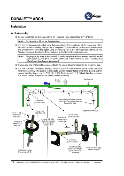
10. Locate the (2) Corner Bellows and the (2) Hydraulic Hose assemblies (27-1/2” long).
Note: For Steps 11 to 13, see the images below.
11. If it has not been completed already, fasten a plastic Corner Adapter at the driver side of the
Upper Channel assembly. The groove in the plastic Corner Adapter faces toward the center of
the arch and will secure the Upper Lens. Use (1) 3/8-16 x 1-1/4” Shoulder Bolt and (1) 3/8 Flat
Washer to secure the plastic Corner Adapter to the Upper Channel Assembly.
Note: The purpose for using a shoulder bolt is so that the plastic Corner Adapter can slide on the
Upper Manifold, away from the center of the arch so the Upper Lens can be installed. See
Utility Connections later in this manual.
12. Fasten one end of the first hose assembly to the Upper Channel assembly on the driver side.
13. If it has not been completed already, fasten a plastic Corner Adapter at the driver side Side
Channel assembly. The groove in the plastic Corner Adapter faces toward the ground and will
secure the Side Lens. Use (1) 5/16-18 x 1-1/4” Fastener and (1) 5/16 Lock Washer to secure
the plastic Corner Adapter to the Side Channel assembly.
Head Assembly
Direction
Of Travel
Parts of the Upper Channel Assembly
Corner Hose and (2) Side Channel Assemblies Are
(1) On Each Side Removed For Clarity
Corner Hose Upright Leg Assembly (2)
5/16-18 x 1-1/4” (1) On Each Side
Fastener (1) On 3/8 Flat Washer
Each Side (1) On Each Side
3/8-16 x 1-1/4”
Smooth Side of the Shoulder Bolt (1)
plastic Corner Adapter On Each Side
5/16 Lock
Washer (1) On (1) On Each End of
Each Side Corner Bellow
Corner Hose
(1) On Each Side
Smooth Side of the Partial View of the Upper
plastic Corner Adapter
Partial View of the Side (1) On Each End of Channel Assembly
Channel Assembly (2) Corner Bellow
18 Belanger, Inc.® *PO BOX 5470 *Northville, MI 48167-5470 * Ph (248) 349-7010 * Fax (248) 380-9681 1MANUL028