
Page 26 - DuraJet™ / AlumaJet™ Arches
P. 26
DURAJET™ ARCH
Installation
Utility Connections
Water
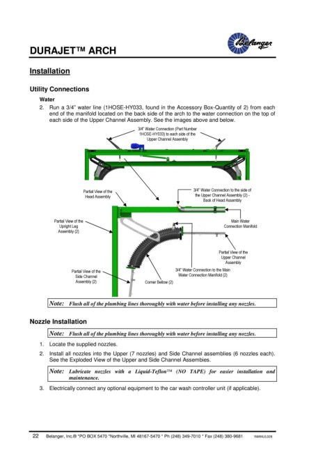
2. Run a 3/4” water line (1HOSE-HY033, found in the Accessory Box-Quantity of 2) from each
end of the manifold located on the back side of the arch to the water connection on the top of
each side of the Upper Channel Assembly. See the images above and below.
3/4” Water Connection (Part Number
1HOSE-HY033) to each side of the
Upper Channel Assembly
Partial View of the 3/4” Water Connection to the side of
Head Assembly the Upper Channel Assembly (2) -
Back of Head Assembly
Partial View of the Main Water
Upright Leg Connection Manifold
Assembly (2)
Partial View of the
Upper Channel
Assembly
Partial View of the 3/4” Water Connection to the Main
Side Channel Water Connection Manifold (2)
Assembly (2) Corner Bellow (2)
Note: Flush all of the plumbing lines thoroughly with water before installing any nozzles.
Nozzle Installation
Note: Flush all of the plumbing lines thoroughly with water before installing any nozzles.
1. Locate the supplied nozzles.
2. Install all nozzles into the Upper (7 nozzles) and Side Channel assemblies (6 nozzles each).
See the Exploded View of the Upper and Side Channel Assembies.
Note: Lubricate nozzles with a Liquid-Teflon™ (NO TAPE) for easier installation and
maintenance.
3. Electrically connect any optional equipment to the car wash controller unit (if applicable).
22 Belanger, Inc.® *PO BOX 5470 *Northville, MI 48167-5470 * Ph (248) 349-7010 * Fax (248) 380-9681 1MANUL028